System reliability engineering for industrial equipment and complex assets
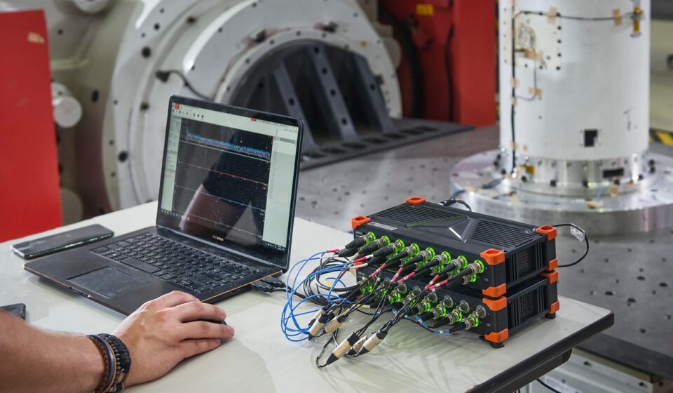
What system reliability engineering means in practice
System reliability engineering is the discipline of designing, verifying and improving a complete system so it performs its required functions under stated conditions for the required time. In industrial equipment, that system can include mechanical assemblies, electrical controls, embedded software, sensors, utilities, operators, maintenance procedures and spare parts. The aim is not simply to buy more reliable components. It is to make the integrated asset dependable enough for its duty, safety context and business consequences.
For teams working across design, operations and maintenance, the subject sits naturally within reliability engineering, but it takes a broader systems view. It asks how requirements, interfaces, redundancy, diagnostics, maintainability, support resources and field feedback work together. That whole-system view is why standards and guidance such as ISO/IEC/IEEE 15288:2023, IEC 60300-1:2024, NASA systems engineering guidance, IEC 60812:2018 and ISO 14224:2016 are useful reference points, even when an industrial company is not formally certified to each document.
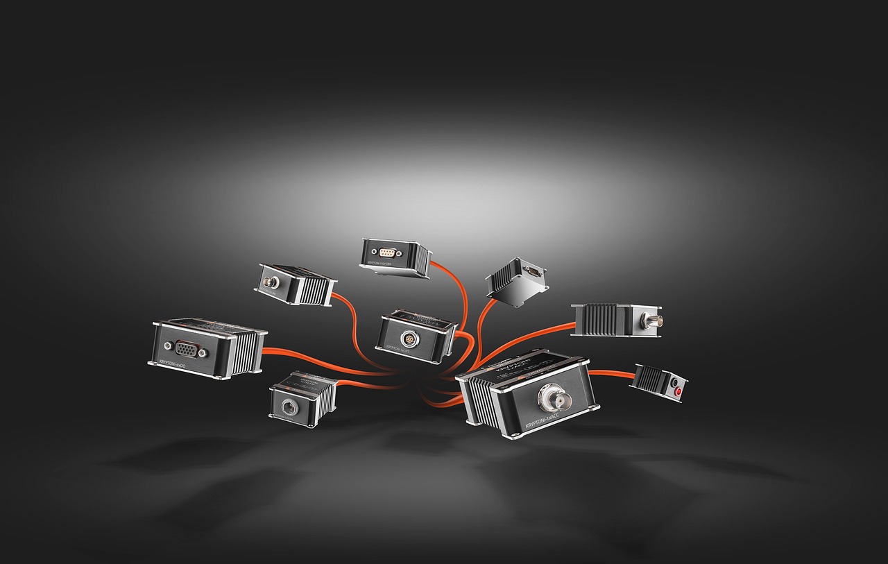
Why a system view matters more than component MTBF alone
Many reliability discussions start with component failure rates or mean time between failures. Those measures can be useful, but they can also hide system-level risk. A machine built from individually robust parts can still fail frequently if interfaces are unstable, operating loads are poorly understood, cooling is marginal, maintenance access is difficult or control software does not handle abnormal states correctly.
A system view changes the question. Instead of asking only which part has the highest MTBF, the team asks which function must continue, what can fail, how the failure is detected, what happens next and how quickly the system can recover. In a production line, the answer may involve buffers, bypasses, modular replacement, condition monitoring and operator response procedures. In a safety-related process, it may involve fail-safe states, diagnostic coverage and proof testing. In remote or hard-to-access equipment, it may involve derating, redundancy, simplified maintenance and disciplined data collection.
This distinction is especially important for industrial equipment because downtime is rarely caused by one isolated variable. Failures often emerge from interactions: vibration combined with poor installation, heat combined with enclosure contamination, software changes combined with undocumented operating modes, or maintenance delay combined with spare-part shortages. System reliability engineering gives teams a structure for identifying those interactions before they become recurring failures.
Core elements of a system reliability program
A practical program does not need to be complicated, but it does need to be explicit. Strong programs connect requirements, architecture, analysis, verification and operating feedback instead of treating each one as a separate document exercise.
Reliability requirements that can be verified
Reliability requirements should be measurable and tied to operating conditions. A weak requirement says that a compressor package shall be reliable. A stronger requirement defines required availability, allowable unplanned downtime, duty cycle, ambient conditions, operating profile, maintenance assumptions and the period over which performance is measured. NASA systems engineering guidance emphasizes measurable and verifiable reliability and maintainability requirements, a principle that applies well beyond aerospace.
For industrial assets, useful requirement categories include mission time, demand rate, acceptable failure consequences, repair time targets, inspection intervals, spare-part assumptions, environmental limits and data-reporting needs. If a requirement cannot be tested, modeled, inspected or measured in service, it is unlikely to drive design decisions.
Architecture and interfaces
Architecture determines many reliability outcomes before detailed design begins. Series dependencies, common power supplies, shared cooling, communication networks, human-machine interfaces and maintenance access points can become single points of failure. A reliability block diagram can show how equipment functions depend on subsystems, while interface control documents can reduce hidden coupling between mechanical, electrical and software elements.
Redundancy is not automatically beneficial. It can improve availability when failure detection, switching logic, inspection and maintenance are well designed. It can reduce reliability when it adds uncontrolled complexity, latent failures or more frequent human error. The system engineer therefore evaluates redundancy as a trade-off, not as a default answer.
Failure analysis and risk prioritization
Failure modes and effects analysis is one of the most common tools for connecting design intent to possible failure behavior. IEC 60812:2018 describes FMEA and FMECA as methods for identifying how items or processes might fail, what the effects may be and how treatments can be prioritized. In system reliability engineering, FMEA is most valuable when it includes interfaces, controls, maintenance actions and operating context rather than only component names.
Fault tree analysis takes a complementary top-down view. It starts with an undesired event, such as loss of cooling, loss of containment or inability to start on demand, then traces combinations of causes that could produce that event. IEC 61025 is a recognized reference for fault tree analysis. Used together, FMEA and fault tree analysis help teams avoid two common errors: missing local failure modes and missing system-level combinations.
Verification, validation and reliability growth
Testing should be planned around the reliability risks that matter most. Environmental tests, endurance tests, accelerated life tests, software fault-injection, maintainability demonstrations and integration tests each answer different questions. A long bench test may reveal wear mechanisms, but it may not reveal field installation errors. A software simulation may expose control-state problems, but it may not prove connector durability. A maintainability trial may show that a repair time target is unrealistic because access is blocked or diagnostic information is unclear.
Reliability growth is the disciplined process of finding, analyzing and correcting failure causes during development or early operation. It is not the same as repeatedly testing until a product passes once. A useful reliability growth loop records the failure, identifies the root cause, applies a corrective action, verifies that the corrective action works and updates requirements, drawings, software, procedures or training as needed.
Methods and metrics used in system reliability engineering
Metrics should describe the system behavior that the organization needs to manage. No single metric is sufficient. MTBF may be useful for repairable equipment under stable conditions, but it does not describe downtime duration, maintenance resources, consequence severity or the shape of the failure distribution. Availability, maintainability and failure consequence often matter just as much.
| Metric or method | What it helps answer | Typical limitation |
|---|---|---|
| Reliability function | Probability that the system performs a required function for a stated time under stated conditions | Requires a clear mission definition and valid assumptions |
| MTBF or failure rate | How often repairable items are expected to fail in a defined population or period | Can be misleading if failures are not random or operating conditions vary widely |
| Availability | Whether the system is ready to perform when needed | Depends on both reliability and repair or support performance |
| MTTR and maintainability | How quickly the system can be restored after failure | Can ignore logistics delay if measured too narrowly |
| FMEA or FMECA | Which failure modes, effects and controls need attention | Quality depends heavily on team knowledge and current design information |
| Fault tree analysis | Which combinations of events can cause a top-level failure | Can become complex if boundaries and assumptions are not controlled |
| Reliability block diagram | How subsystem success or failure affects system success | May oversimplify dependencies, software behavior or common-cause failures |
For industrial equipment, data discipline is often the difference between useful reliability engineering and guesswork. ISO 14224:2016, although written for the petroleum, petrochemical and natural gas industries, is widely referenced because it gives a structured approach to collecting equipment, failure and maintenance data. Its underlying lesson is broadly applicable: reliability data must identify equipment taxonomy, operating context, failure mode, cause, consequence, maintenance action and downtime in a consistent language.
Without that structure, teams may know that a system is down too often but still be unable to separate design weakness from misuse, poor installation, contamination, spare-part delay or preventive maintenance error. With structured data, Pareto analysis, Weibull analysis, bad-actor lists and maintenance optimization become more defensible. See also: automation and controls.
How standards and guidance fit together
No single standard covers every reliability question for every industrial system. A better approach is to understand what each reference is designed to support, then tailor it to the asset, risk level and organization.
- ISO/IEC/IEEE 15288:2023 provides a framework for system life cycle processes from conception through retirement. It is useful for connecting reliability work to stakeholder needs, requirements, architecture, verification, validation, operation and support.
- IEC 60300-1:2024 addresses dependability management across systems, products and services. Its scope includes hardware, software, data, processes, facilities, materials and personnel, which aligns closely with the reality of industrial equipment.
- IEC 60812:2018 supports FMEA and FMECA planning, performance, documentation and maintenance. It is particularly helpful when teams need a repeatable way to identify and prioritize failure modes.
- IEC 61025 supports fault tree analysis for top-down assessment of undesired events and combinations of causes.
- ISO 14224:2016 supports structured collection and exchange of reliability and maintenance data for equipment in oil, gas and petrochemical operations, with concepts that can inform CMMS and EAM data models in other sectors.
- SAE JA1011 gives evaluation criteria for reliability-centered maintenance processes. It is most relevant when reliability analysis is being translated into maintenance tasks for physical assets.
- IEEE 1633-2016 addresses software reliability practices, which matters because many modern industrial failures involve control logic, firmware, data handling or software-hardware interaction.
The practical point is that system reliability engineering is not a single worksheet. It is a managed set of processes that connects technical risk, operating evidence and life-cycle decisions.
A practical workflow for industrial teams
Organizations can begin with a staged workflow rather than a large formal program. The following sequence is suitable for new equipment development, major upgrades and chronic reliability problems in existing assets.
- Define the system boundary. Include equipment, controls, utilities, software, operators, maintenance access, spares and interfaces. Excluding support elements too early can hide the real cause of downtime.
- Describe required functions and operating profiles. Identify duty cycles, start-stop frequency, loads, environmental conditions, cleaning cycles, changeovers and abnormal but credible operating states.
- Set measurable reliability and availability targets. Link targets to business or mission consequences. A packaging line, a standby generator and a safety instrumented subsystem will not need the same target.
- Map architecture and critical interfaces. Look for single points of failure, common-cause vulnerabilities, hidden dependencies and maintenance barriers.
- Perform FMEA and selected fault tree analysis. Use FMEA for local and functional failure modes. Use fault tree analysis for high-consequence top events or repeated system-level failures.
- Plan verification and validation around risk. Match tests to the main uncertainty: endurance, environment, software states, integration, installation quality or maintainability.
- Create a field data plan before launch or restart. Define failure codes, maintenance action codes, downtime rules and required evidence. Align the CMMS or EAM system with how reliability decisions will be made.
- Feed operating evidence back into design and maintenance. Update limits, procedures, spare-part strategy, inspection plans, training and future design standards.
This workflow can be scaled. A high-volume production asset may justify detailed modeling and formal design reviews. A smaller plant asset may need a concise functional analysis, a disciplined FMEA, better failure coding and a monthly reliability review. The principle is the same: make assumptions visible, test what matters and learn from field evidence.
Common mistakes that weaken system reliability work
The first mistake is treating reliability as a late-stage calculation. If the architecture is already fixed, access is poor and operating loads are underestimated, a prediction model can only document the risk. It cannot remove it cheaply.
The second mistake is using generic failure rates without checking whether the operating environment matches the data source. Temperature, vibration, contamination, duty cycle, maintenance quality and installation practice can all change failure behavior. Historical data should be relevant, current and traceable.
The third mistake is confusing availability with reliability. A system can fail often but be restored quickly, producing acceptable availability in a low-consequence application. Another system can fail rarely but take days to repair, creating unacceptable production or safety exposure. Design teams need both reliability and maintainability targets.
The fourth mistake is allowing FMEA documents to become static archives. An FMEA created during design should be updated when tests reveal new failure modes, suppliers change, software is revised or field failures occur. The same applies to fault trees, reliability block diagrams and maintenance strategies.
The fifth mistake is ignoring human and organizational factors. Industrial systems are operated, cleaned, adjusted, bypassed, repaired and modified by people. Procedures, training, diagnostics, labeling, access and management of change can either strengthen reliability or create new failure paths.
Frequently asked questions
Is system reliability engineering the same as reliability engineering?
System reliability engineering is a systems-focused branch of reliability engineering. It considers how all elements of a system work together, including hardware, software, interfaces, people, maintenance and support resources. Traditional component reliability remains important, but it is only one part of the system picture.
When should reliability engineering start in a project?
It should start when stakeholder needs, operating profiles and architecture options are being defined. Early work should focus on measurable reliability requirements, system boundaries, functional analysis and critical interfaces. Waiting until prototype testing or commissioning usually makes changes more expensive and less effective.
Which tools are most useful for industrial equipment?
The most common practical tools are reliability requirements, reliability block diagrams, FMEA or FMECA, fault tree analysis, maintainability review, reliability growth tracking, structured field data and reliability-centered maintenance. The right mix depends on asset criticality, failure consequences, complexity and available evidence.
Can system reliability be improved without replacing equipment?
Yes. Improvements may come from better operating limits, contamination control, alignment, lubrication, software updates, diagnostic alarms, spare-part strategy, maintenance procedures, training or data quality. Replacement is sometimes necessary, but many system failures are caused by interactions that can be controlled through design changes, operating discipline or maintenance optimization.
What is the most important first step?
Define the system boundary and the required function in measurable terms. If the team cannot agree on what the system must do, under which conditions and for how long, later analysis will be inconsistent. Clear boundaries and requirements make every following step more useful.